Lm324 lm324n ic datasheet circuito integrado amplificador pwm pinout amplifier comparator ecured opamp konfigurasi comparador 14pin Lm324 ic Lm324 ic pin diagram & description| lm324n datasheet
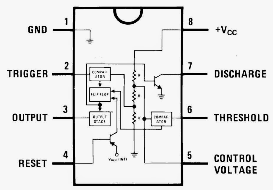
Where is pin #1 for NE555P - Page 1
Wass robotics: ic 555 Amplifier lm324 instructables preamp Treble bass scematic
Timer ne555 circuit ic555 blok robotics wass rangkaian kerja tegangan ttl belajar kemasan dip8 komponen
555 timer 35v ne555 conversor circuits how2electronicsLm 324 amplifier? Where is pin #1 for ne555pScematic diagram: tone control circuit lm 324.
555 ic timer diagram circuit astable pinout pins block using description ic555 multivibrator internal ground explain structure ne555p where itsLm324 lm324n Simple dc-dc converter using 555 timer ic (7.5-35v).


Lm 324 amplifier? - Instructables

Where is pin #1 for NE555P - Page 1
Scematic Diagram: Tone Control Circuit Lm 324

LM324 IC Pin Diagram & Description| LM324N Datasheet

WASS ROBOTICS: IC 555

Simple DC-DC Converter using 555 Timer IC (7.5-35V)